Subwoofer Installation Details
Some of my photos of this were lost due to a hard drive crash.
Removing the parcel shelf is not particularly difficult, but you need a little more information than the service manual provides. Here is my procedure:
1. Fold rear seats forward.
2. Disconnect harness from center-mounted brake light.
3. Remove the tethers. These are the three black things on the parcel shelf.
Remove them by pulling the black plastic covers up vertically (you may need
to pry them) and then removing the 13mm bolts.
4. Pull up on the parcel shelf trim nearest the front of the car to unclip three
clips and then slide the parcel shelf out forward (to front of car). Check these
for damage before reinstalling.
I cut the large round hole for the subwoofer in the parcel shelf by marking it (using the cardboard template) with a black marker and then removing and cutting it with a utility knife. The parcel shelf is a layered cardboard and fabric composite. After the hole is present in the parcel shelf, it can be completely reinstalled for marking of the car. Then remove it again, and cut the metal in the car with shears, and file away the sharp edges.
I had to fabricate three parts to complete this installation.
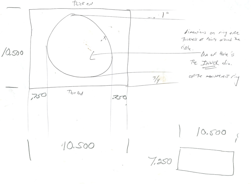
Subwoofer mounting wedge. This is made of PVC plastic and is located between the parcel shelf and subwoofer enclosure mount. The metal of the trunk roof was cut away just enough to get this piece through. This part occupies the space where the trunk metal used to be, and makes an airtight seal between the parcel shelf and the subwoofer enclosure mount.
This is the design print for this part:
I used a template of the actual speaker to transfer the diameter of the subwoofer to this part for cutting the hole, which is about 9.0" in diameter (not critical). The template also transferred the subwoofer's mounting holes, which were drilled and tapped into this subwoofer mounting wedge. These holes are not visible in the following photographs because they were not yet present. All of these parts had to be repeatedly installed and removed from the car to exactly fit the parts together and mark locations for additional modification.
This part is shown mounted in the car, as viewed from the inside of the car facing rearward:
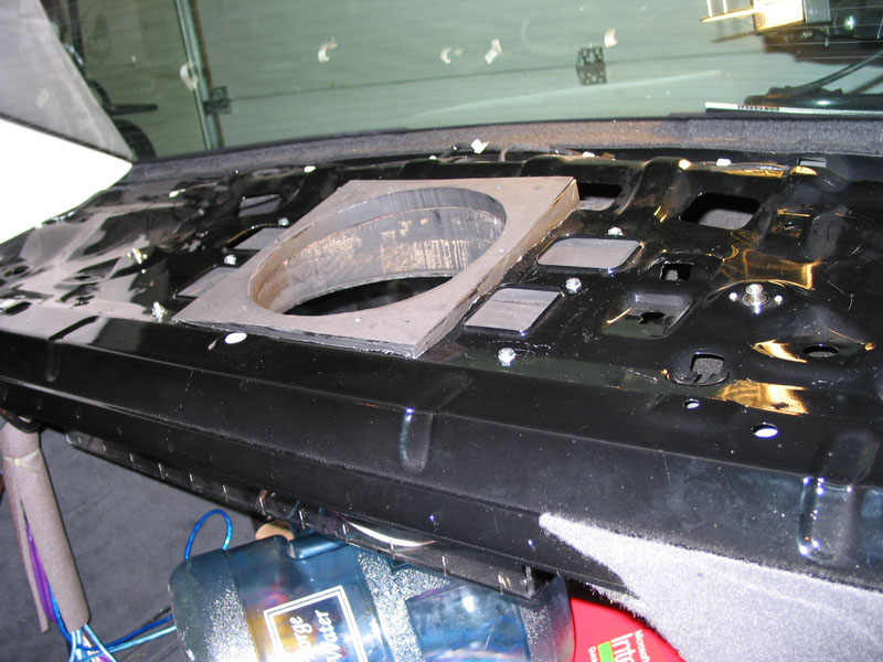
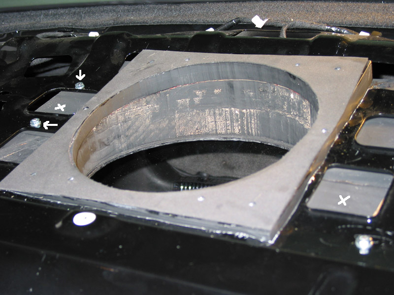
Ten recessed screws secure this part to the subwoofer enclosure mount and are visible in the photographs. A thin foam gasket and some rubber cement were placed between the parts to achieve an airtight fit. The two parts touch, but you can tell them apart in the photographs. The photographs also show the nuts that are bolting the entire assembly to the car - these bolts go upward from inside the subwoofer enclosure, through the subwoofer enclosure mount, through the subwoofer mounting wedge, and finally through the metal of the car. Four bolts, cut to length, are present (arrows). The wooden subwoofer enclosure mount (painted black) is visible through the holes in the car metal (X's).
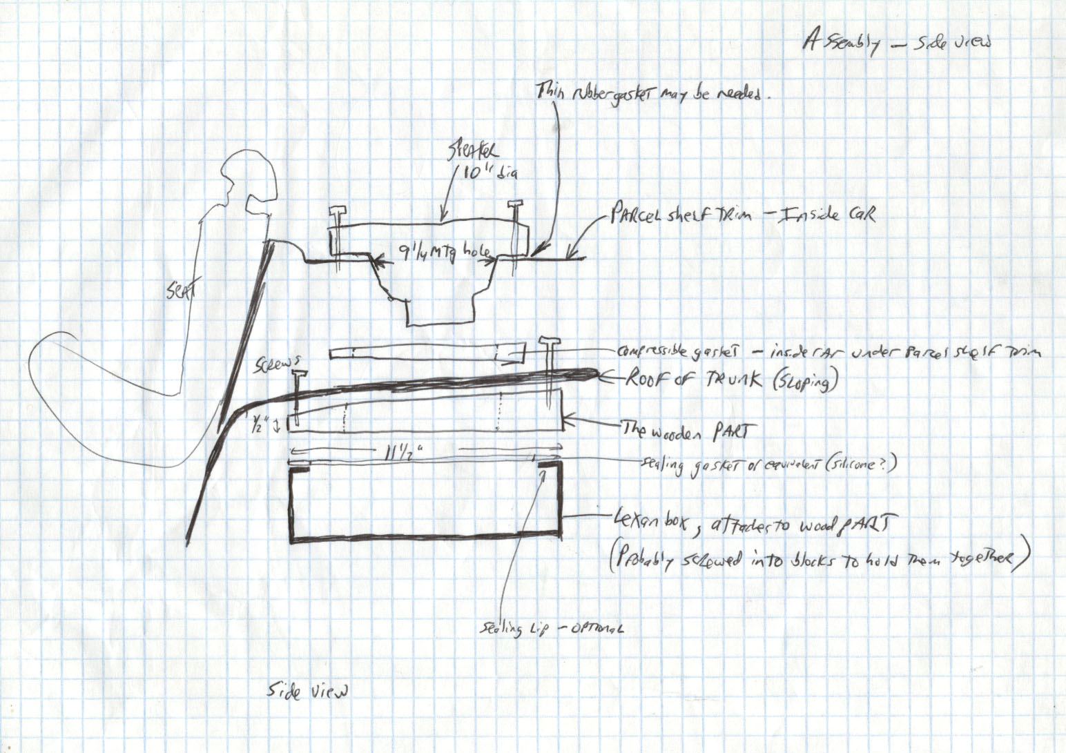
This is the (side view) assembly drawing of how the pieces go together, not quite accurate:
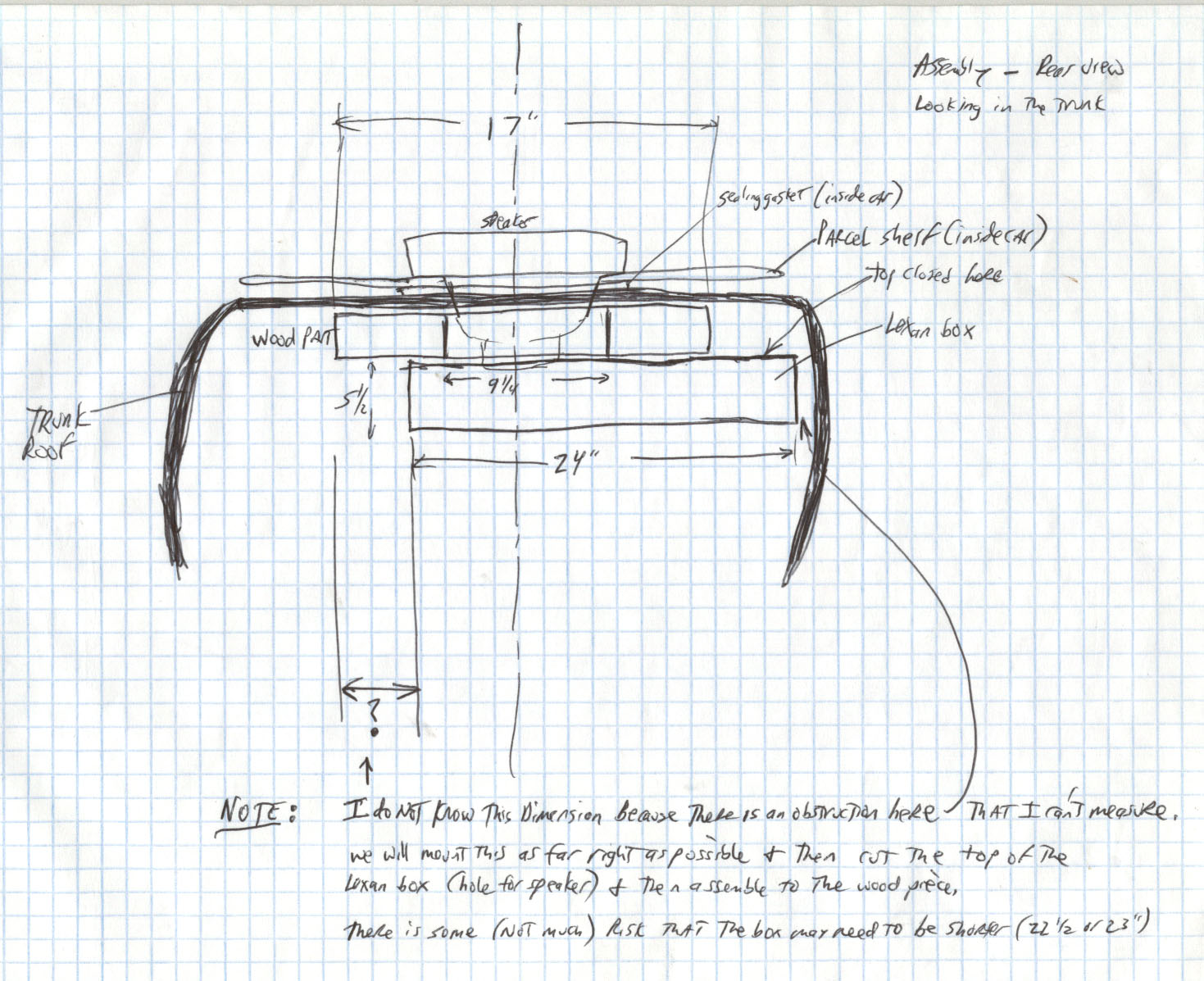
This is the (rear view) assembly drawing of how the pieces go together:
Subwoofer enclosure mount.
This is a wedge made of wood (in fact, a thick slice out of a large tree). It attaches directly to the bottom of the subwoofer mounting wedge, between it and the subwoofer enclosure. Its purpose is to make an airtight seal with the enclosure and to provide a level surface on the roof of the trunk on which to mount the enclosure. Screws hold it and the enclosure to themetal of the trunk roof for strength.
This part is much larger than the subwoofer mounting wedge because it is bolted to the car and to the enclosure. The enclosure is not centered on it, which is a feature to conserve space in the trunk.
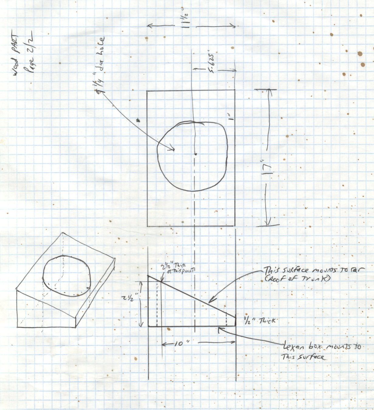
The following is my original drawing of this part:
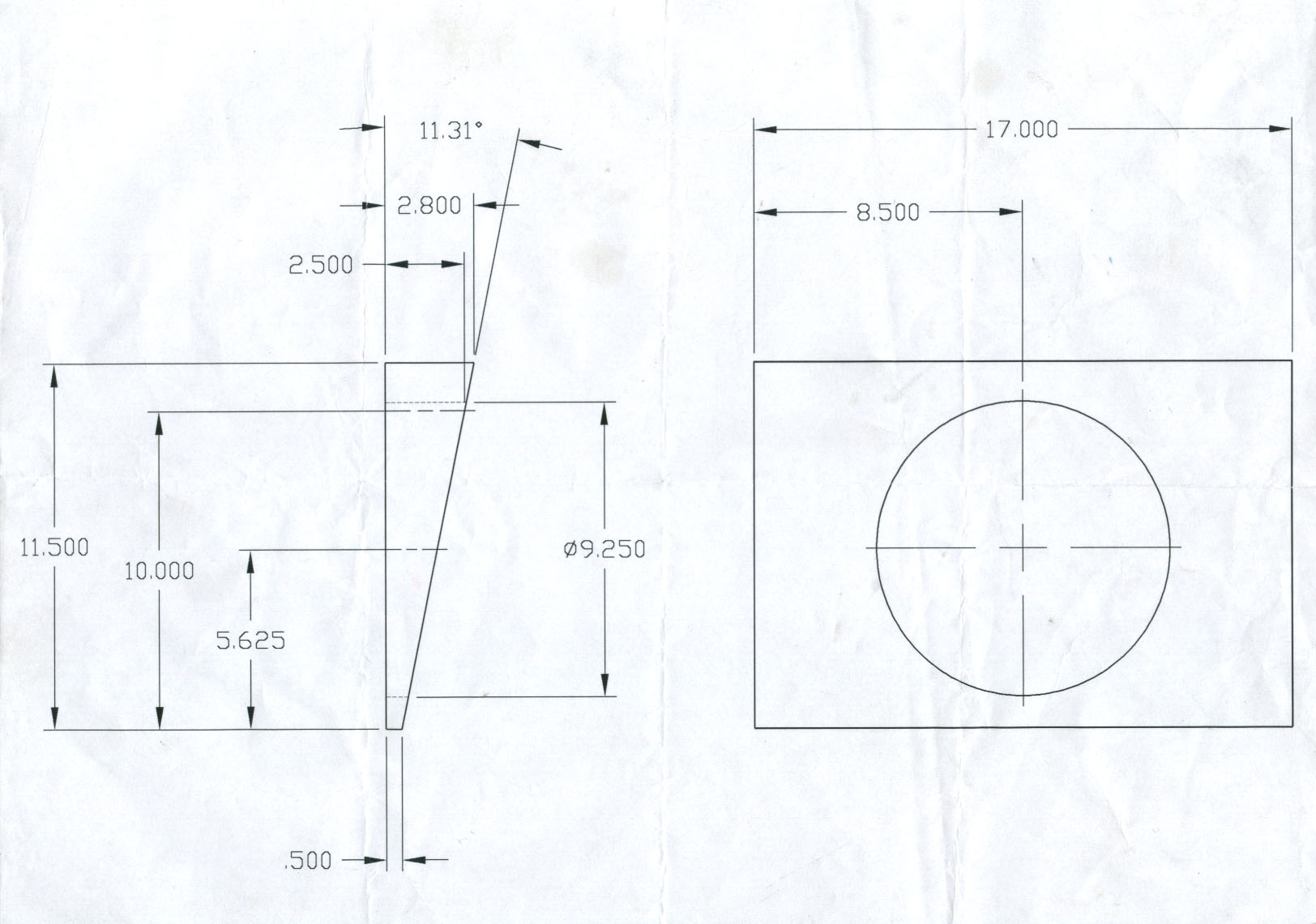
This is a mechanical drawing of this part:
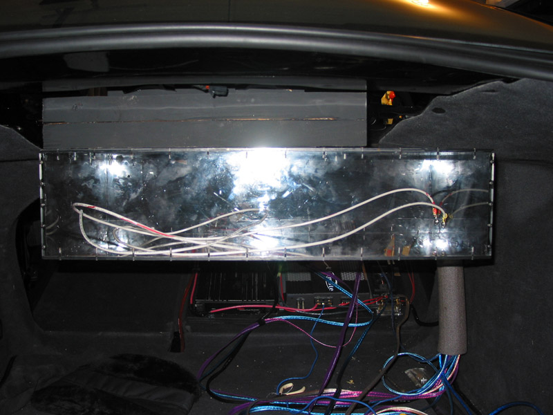
The subwoofer enclosure mount and the subwoofer enclosure are both visible in this photograph of them installed in the car, as viewed from the rear:
Subwoofer enclosure
We fabricated an airtight solid Lexan box with a removable bottom, then used a rotary electric cutter (like a zip tool used for cutting electrical outlet holes in drywall) to cut a round hole to accommodate the subwoofer after locating the box at the correct place in the car and marking it through its open bottom.
After mounting it, I made the electrical connections to the speaker and ran them to screws which I put through the box on the far right side. The connection to amplifier is another set of wires that attach to these screws, outside the box. The terminals are held on by nuts. Drill the holes in the box just large enough to clear the screws. Inside the box, use a minimum length of wire (to avoid it vibrating on the bottom). After everything else is completed, the bottom of the box was screwed on with tiny screws located all around the perimeter.
Recalling that I had vibration issues with the Lexan subwoofer enclosure, you may consider making it out of wood. I had to reinforce this one with aluminum braces and plates. However, the assembly concept and the two mounts would be the same regardless of the subwoofer enclosure's construction.
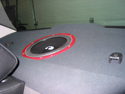
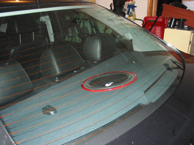
These are final views of the subwoofer installation:
Links for detail pages and illustrations:
Front Speaker Installation Details
Subwoofer Installation Details
Amplifier and Wiring Installation Details
Back to Audio Installation Page
I am the owner and technical administrator of the Official Blondie Web Site (http://blondie.net).