Front Speaker Installation Details
All of my photos were lost due to a hard drive crash. I took some new ones, but until I disassemble the doors again for some reason, I won't have any of the inside. [Note: in July 2004, I had a window problem in the right door, so I retook photos of the woofer installation. These have now been added.]
Here are the design prints. Click on the photos for more detailed photos.
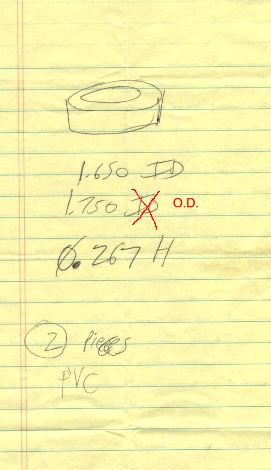
Tweeter mounting ring. This is a simple part so this is the only drawing I made. Two pieces are needed, and we made it out of gray PVC plastic. There is an error in this drawing! It's actually 1.750 O.D. (not I.D.). It's thin, short ring.
The tweeter comes with parts to mount it flush or surface mount, but as I mentioned, I mounted it in the factory location (the triangular speaker mount on the left and right front doors). The tweeters come with mounting templates, but since I did not mount them with any of the mountings they came with, I did not use these.
The factory tweeter mount ("triangular speaker trim") has to be modified to install the new tweeters. First, I carefully pried off the factory tweeter with a screwdriver (using a twisting motion), which essentially broke it free from the factory mount on which it was an integral part. It snaps off cleanly, leaving a hole that is too small for the new CDT one. I used a small grinder to make the hole larger, so the tweeter mounting ring fits inside. After vacuuming the dust out of the factory tweeter mount (which was not as easy as it sounds), I put the tweeter mounting ring inside the hole in the factory mount, and epoxied it in place. I had the tweeter installed into the ring when I did this to guarantee the tweeter mounting ring was not distorted out of round when it was inserted into the triangular speaker trim, but do not epoxy the tweeter into the ring! The tweeter is designed to be removable from the mounting ring, should it ever fail.
To install the CDT tweeter into the ring, I removed the tweeter's grille (which is epoxied to it from the factory) by prying it off with a screwdriver in several places around its perimeter, using a twisting motion between it and the larger metal rim on the tweeter itself). Be careful not to damage it during removal or touch the tweeter cone after its protective grille is removed. Note how the tweeter mounting ring fits over the tweeter, stopping at the lip, and how its height extends just far enough out to protect the tweeter cone when the assembly is inserted into the factory tweeter mount. If your tweeter dome doesn't extend exactly 0.267" from the lip, the height of your tweeter mounting ring should be adjusted accordingly. The tweeter mounting ring fits firmly over the tweeter, but force is not required. Make sure there isn't any epoxy on the edge of the tweeter after removing its grille, otherwise it won't go in the mounting ring. I used a fine file to remove some bits of it because the I.D. of the mounting ring was determined by measuring the metal O.D. on the tweeter itself.
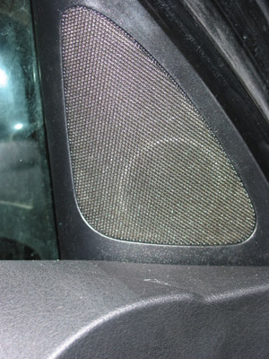
You can just see the tweeter mounting ring through the triangular speaker trim. It's located near the bottom to accommodate the increased mounting depth of the CDT tweeter.
To remove this speaker trim, first remove the door panel trim, disconnect the wiring harness (a two-pin connector), remove the single mounting screw near the front of the car, then slide the triangular trim piece straight up until released, then rearward (directly away from door hinge). Installation is the reverse of removal. Rear door installation is different because the rear speakers are integrated into the rear door panel.
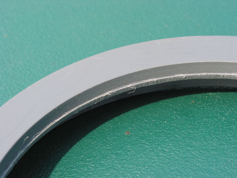
Woofer speaker mount.
The 6.5" woofer speaker mount is a thick ring, 5.75" I.D., 6.80" O.D., and 1.1" deep. We fabricated it out of wood (two sheets glued together), since a 1.1" thick piece of PVC plastic (which would have been great) is hard to come by. Two pieces are required, one for each side.
 -
-
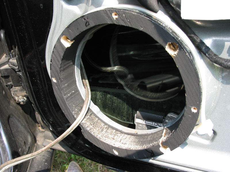
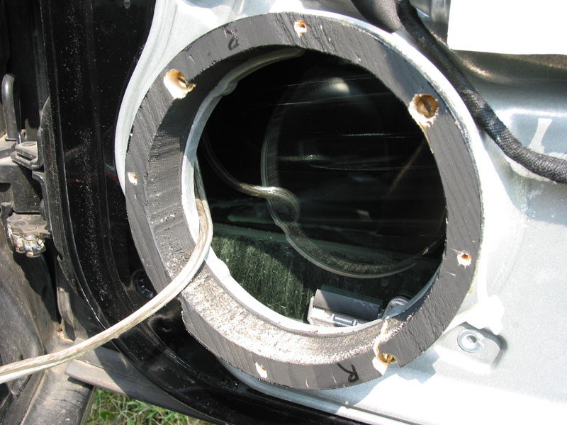
(two views, click on image for more detail. note recessed screws mounting the
ring to the door, and holes for mounting the speaker to the ring).
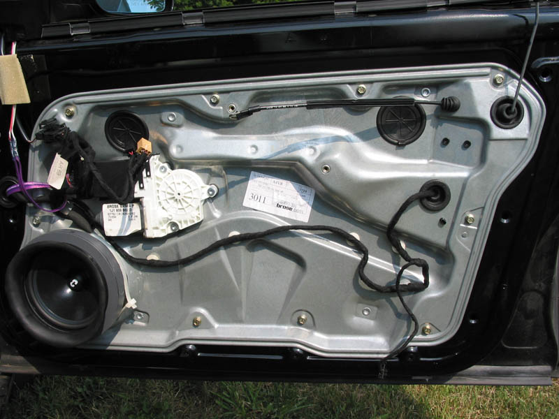
The factory woofer is integrally mounted into a black plastic housing which is riveted into the car door. To remove it, the rivets must be drilled out (in 4 places). I used a #26 drill, and if the rivets started to turn, I held them in place by prying with a screwdriver, and continued drilling. One of them was stubborn, so I used a #19 on it and then pressed it backwards through the hole. Discard the factory speaker and plastic mounting, and don't forget to vacuum the chips out of the inside of the car door. Keep the plastic/rubber sound guide that snaps over the plastic mounting.
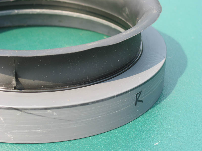
The purpose of this woofer speaker mount is to enable the new 6.5" woofer to be mounted to the door, since it is impossible to rivet it (due to thickness) and also impossible to get behind it once the speaker is installed (due to obstruction). The woofer speaker mount gets four small clearance holes drilled through its 1.1" depth, in 4 places 90 degrees apart, corresponding to the holes that are left in the car door. These holes are also enlarged for part of the depth, so that the screw heads go into the speaker mount and do not protrude, where they would interfere with the attaching of the speaker. Screws, washers, lock washers, and nuts hold the woofer speaker mount to the door. I also made a felt ring or gasket that went between the woofer speaker mount and the metal of the car door. Another felt ring is between the speaker and the wooden mounting ring (visible in the following photograph). Important: I put a strong cable tie around the speaker mount and pulled it tight before tightening the screws that hold the speaker mount onto the car door. Don't overtighten the screws or the wood ring will break. It is important to use thetie around the diameter if you make it out of wood because over time it will split, and without it, it may not hold the speaker securely enough then. See the following image for the assembly:
Four more smaller holes are drilled into the woofer speaker mount for mounting the speaker to it once it has been secured to the car door. This set of holes should be located 45 degrees rotated from the set of holes that secure the mount to the door. Use the actual speaker to mark them. Make sure they are large enough for the screws that will hold the speaker down (to avoid cracking the wood), but not so large that they can't be tightened. Test the fit before attempting to mount the speaker. I used #4 x 1/2" stainless steel pan head screws to attach the speaker. See photos above.
After wiring was complete, I soldered the terminals on the ends of the speaker wiring to the speaker. If you don't do this, the terminals will pull off as soon as you open the window and you will have to disassemble the door again. However, if you ever need service (such as to replace the window regulator, which is a Volkswagen recall procedure), expect to get hassled by the car dealer, and to cut the wires off, and then for them to ignore your request to reattach them. You'll have to tear the door apart again to resolder them (and they will be rude to you, and maybe even lose the factory sound guide). After wiring, tape around the metal terminals thickly and securely with duct tape to avoid shorts in case the terminals bend (like if the window falls down into the door frame), then place the speaker over the speaker mount and fasten it with short self-tapping screws. I installed another felt ring between the speaker and the mount. Don't overtighten or the woofer speaker mount will split.
The speaker's outside diameter is slightly smaller than the outside diameter of the woofer speaker mount (the mounting ring). This is important so it's possible to put the last part on...
Woofer cover/adapter
Partial design print:
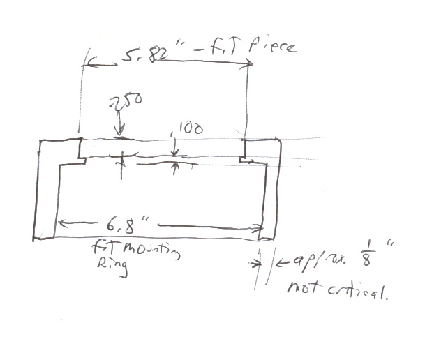
This part is used to attach the factory sound guide over the speaker and the woofer speaker mount, and to hold it in place so it extends outward from the door the same amount that it did in the factory installation. Two pieces are required (one for each side), and we made this one out of PVC. There is a 0.250" deep 5.82" (fit to sound guide) cut in the top for holding the sound guide, bottoming out on a thin lip (0.050 narrower radius, diameter 5.72"). The bottom is opened to 6.80" (fit to wooden speaker mounting ring). The O.D. is not critical and is about 1/8" thick all around (approx 7" O.D.). The entire piece is about 1" thick, again not a critical dimension.
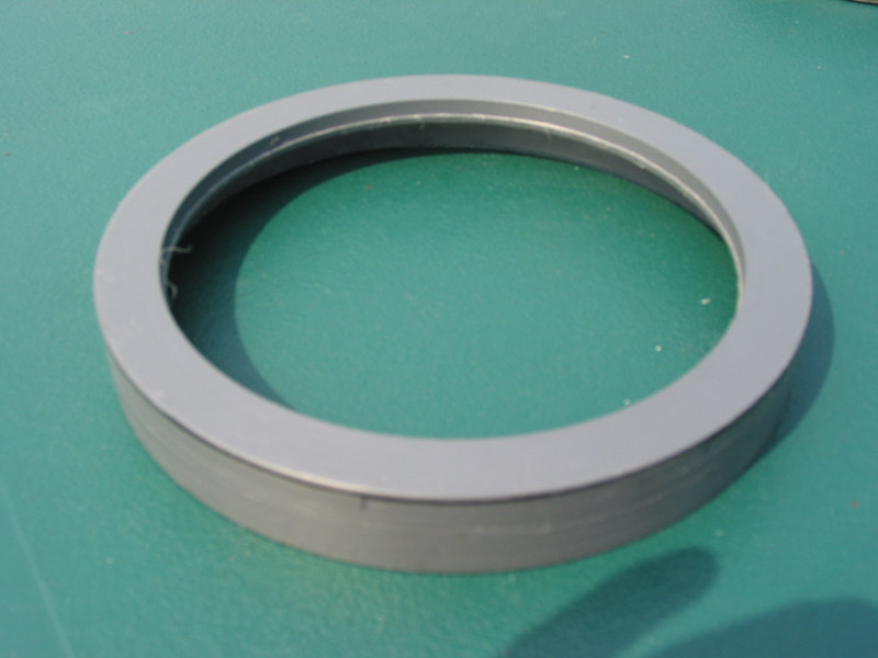
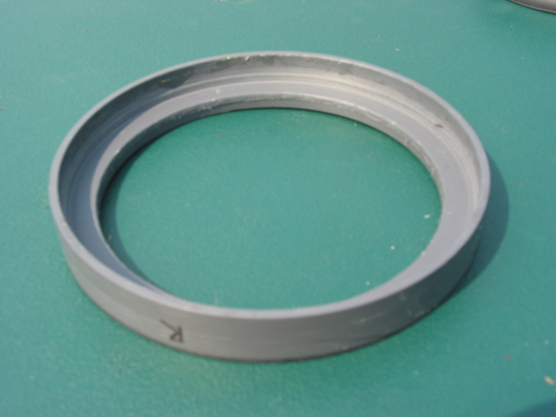
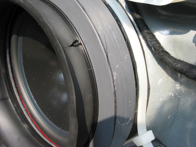
The woofer cover/adapter slides over (and around) the woofer mounting and the factory sound guide presses into a groove in the woofer cover/adapter. The part acts as a reducer because the sound guide's I.D. is significantly smaller than the O.D. of the woofer speaker mount. It doesn't need to fit tight. If it is too loose, use some rubber cement to hold it to the woofer mount.
Make sure the factory sound guide is securely seated into its retaining groove.
Additional information
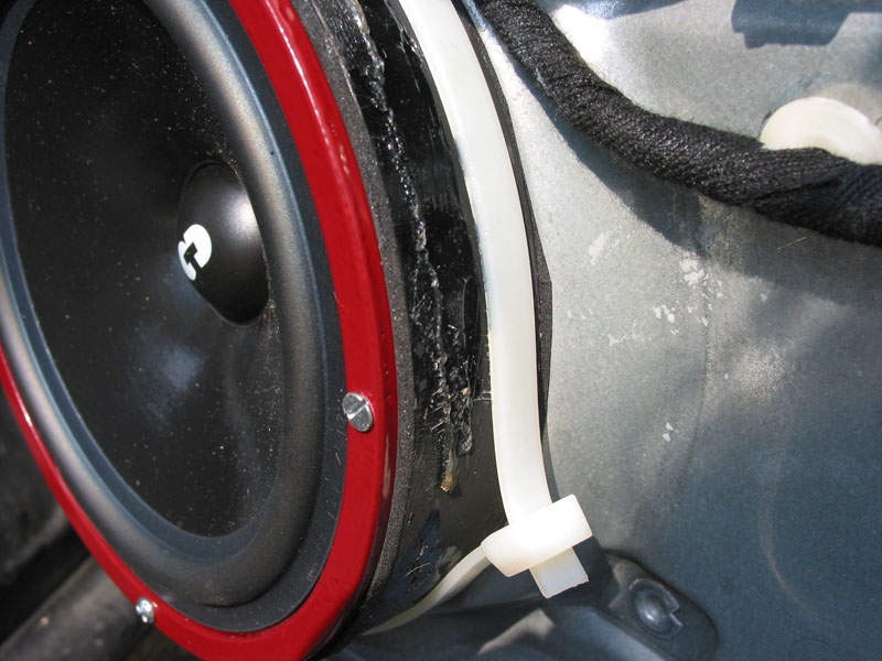
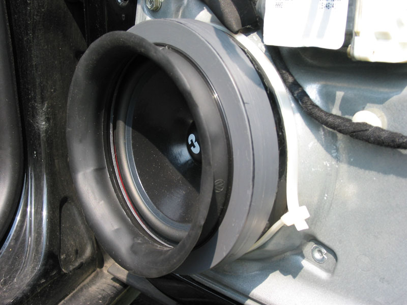
The woofer and tweeter speaker wiring is run out of the door through the rubber wiring harness boot. Remove the boot on the door side (not the car side), then work the wires through it and then under the dash after removing the under-dash trim. The rubber wiring harness boot is visible in this photo (upper arrow):
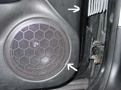
Don't pry on the factory grille. It doesn't come off and will break if you try (lower arrow).
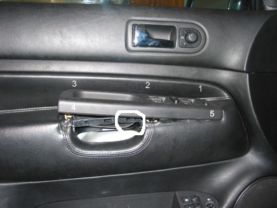
When reinstalling the trim on the left door, install the window control panel last. Align it first, then press straight down on the clips in the order (1-5) as indicated in this drawing. Always be careful not to put any strain on the strut for the door handle. It is fragile at the position circled. I broke it, but it is repairable with cyanoacrylate glue. If you are not familiar with the procedure for removing the trim, you can email me for pointers. Don't press the door trim clips into place without confirming the window control wiring harness isn't trapped in the door and that all the controls including the door latch release work properly.
The quick summary is:
1. Pry the inner door handle trim piece out inserting a very thin blade screwdriver
inserted under the door handle grip and pressing directly toward the door.
2. Remove window control panel by pressing directly upward above the circled
area in the picture to release the first clip, then use your fingers to unclip
the other four clips. Don't break the strut.
3. Remove three large phillips screws that are then exposed.
4. Remove three T-20 Torx screws at the very bottom of the door.
5. Remove one phillips screw at the inner door edge, by the triangular speaker
trim on the door hinge edge, using a stubby phillips.
6. Insert a very long standard screwdriver (taped up to prevent scratching)
under the door trim in the bottom outer (left) edge and prying until the clip
is released. Then use your hands to unclip the rest of the clips. If the clips
fall out on installation, tape them in place.
7. Remove door panel trim by pulling it directly up and out of the window slot.
8. Remove wiring harness connectors and door latch cable. Important: cable is
pulled straight away from door hinge to remove (then, remove hook). When reinstalling,
be sure to connect hook, put cable in guide, then push cable directly toward
door hinge until it snaps locked. Make sure window slot seal is inserted into
window slot and pressed firmly down into place before installing door trim.
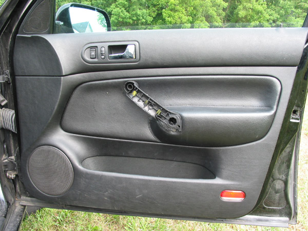
The right door is not quite so complicated, but the door handle trim is more difficult to remove. You must insert a screwdriver under it and pry so as to remove the trim toward you, being careful not to break the plastic marked by the red arrow in the following drawing. The remainder of the process is almost identical to the left side, except there are only two large phillips screws, not three.
The CDT Audio website shows the following information:
HD-642DT (6.5") depth 2 13/16", hole 5 11/16".
CDT-4 (4" cast alloy midrange) depth 2 1/8", hole 3 7/8"
CDT-2 (1" silk soft dome tweeter) depth 3/4", hole 2".
MS-100 (10" cast alloy subwoofer) depth 4", hole 9 1/4".
Be sure to check these against your actual parts!! I needed to buy the speakers
first, and then I made cardboard templates of all of them so I could design
the parts and drill holes in the car in the correct place.
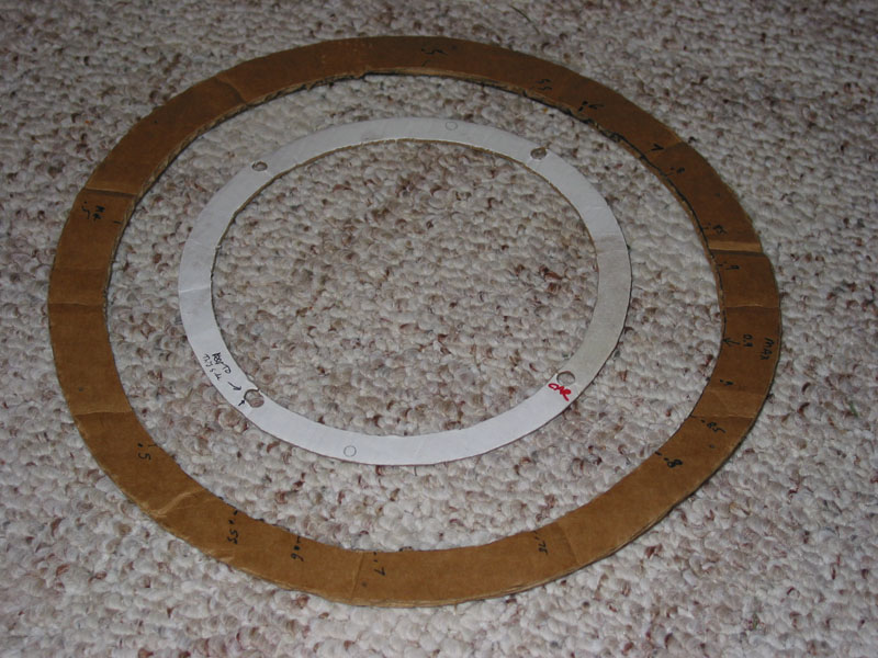
The markings on the subwoofer template are the depths I measured that were needed to fabricate the mounting wedge. I had to cut metal in the car before I could design the part.
Here is the finished dash installation:
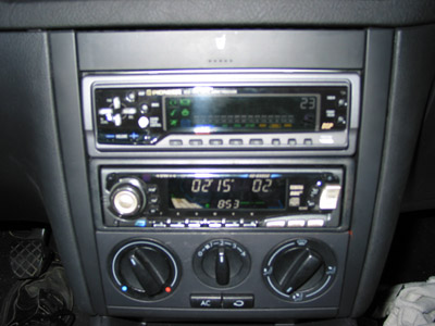
I set the JVC fader to R01 and the Pioneer EQ volume to 23. Write down your stored equalizer settings because they are erased when you press its reset button.
Links for detail pages and illustrations:
Front Speaker Installation Details
Subwoofer Installation Details
Amplifier and Wiring Installation Details
Back to Audio Installation Page
I am the owner and technical administrator of the Official Blondie Web Site (http://blondie.net).